The Improving Mathematics Education in Schools (TIMES) Project
Introduction to Plane Geometry
Measurement and Geometry : Module 9![]() Years : 7-8
Years : 7-8
June 2011

Students will have had extensive informal experience with geometry in earlier years, and this will provide a good intuitive basis for the more systematic approach to geometry appropriate in Years 7−10. The particular topics from Years F−6 relevant to this module are:
- The use of compasses and rulers and the careful drawing of geometrical figures.
- Types of angles, including at least right angles, acute angles, obtuse angles and
reflex angles. - Triangles, including an informal introduction to isosceles and equilateral triangles.
- Quadrilaterals, including an informal introduction to squares, rectangles, parallelograms, trapezia and rhombuses.
- Informal experience with translations, reflections, rotations and enlargements,
and with symmetry in the context of activities such as folding an isosceles triangle, rectangle or rhombus.
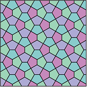 Geometry is used to model the world around us. A view of the roofs of houses reveals triangles, trapezia and rectangles, while tiling patterns in pavements and bathrooms use hexagons, pentagons, triangles and squares.
Builders, tilers, architects, graphic designers and web designers routinely use geometric ideas in their work. Classifying such geometric objects and studying their properties are very important. Geometry also has many applications in art.
Just as arithmetic has numbers as its basic objects of study, so points, lines and circles are the basic building blocks of plane geometry.
In secondary school geometry, we begin with a number of intuitive ideas (points, lines and angles) which are not at all easy to precisely define, followed by some definitions (vertically opposite angles, parallel lines, and so on) and from these we deduce important facts, which are often referred to as theorems. In secondary school, the level of rigour should develop slowly from one year to the next, but at every stage clear setting out is very important and should be stressed.
Thus geometry gives an opportunity for students to develop their geometric intuition, which has applications in many areas of life, and also to learn how to construct logical arguments and make deductions in a setting which is, for the most part, independent
of number.
The simplest objects in plane geometry are points and lines. Because they are so simple, it is hard to give precise definitions of them, so instead we aim to give students a rough description of their properties which are in line with our intuition. A point marks a position but has no size. In practice, when we draw a point it clearly has a definite width, but it represents a point in our imagination. A line has no width and extends infinitely in both directions. When we draw a line it has width and it has ends, so it is not really a line, but represents a line in our imagination. Given two distinct points A and B then there is one (and only one) line which passes through both points. We use capital letters to refer to points and name lines either by stating two points on the line, or by using small letters such as  and m. Thus, the given line below is referred to as the line AB or as the line .

Given two distinct lines, there are two possibilities: They may either meet at a single point or they may never meet, no matter how far they are extended (or produced). Lines which never meet are called parallel. In the second diagram, we write AB ||CD.

Three (or more) points that lie on a straight line are called collinear.
Three (or more) lines that meet at a single point are called concurrent.
|
|
| Collinear | Concurrent |


Exercise 1
Draw three lines that are not concurrent such that no two are parallel.
Exercise 2
Make a large copy of the diagram below. The points X, Y, Z are any points on the line and A, B ,C are any points on the line m. Join AY and XB call their intersection R. Join BZ and YC and call their intersection P. Join CX and ZA and call their intersection Q. What do you notice about the points P, Q, R? (This result is called Pappus’ theorem, c. 340 AD.)

 Suppose A and B are two points on a line. The interval
AB is the part of the line between A and B, including the two endpoints.
 The point A in the diagram divides the line into two pieces called rays. The ray AP is that ray which contains the point P (and the point A).
Angles
 In the diagram, the shaded region between the rays OA and OB is called the angle AOB or the angle BOA. The angle sign
 ![]() is written so we write
is written so we write ![]() AOB.
AOB.
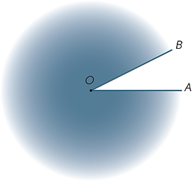 The shaded region outside is called the reflex angle formed by OA and OB. Most of the time, unless we specify the word reflex, all our angles refer to the area between the rays and not outside them.
 Imagine that the ray OB is rotated about the point O until it lies along OA. The amount of turning is called the size of the angle AOB. We can similarly define the size of the reflex angle.
We will often use small Greek letters, α, β, γ, ... to represent the size of an angle.
The size of the angle corresponding to one full revolution was divided (by the Babylonians) into 360 equal parts, which we call degrees. (They probably chose 360 since it was close to the number of days in a year.) Hence, the size of a straight-angle is 180° and the size of a right-angle is 90°. Other angles can be measured (approximately) using a protractor.
|
||
| Straight angle | Right angle | Obtuse angle |

Angles are classified according to their size. We say that an angle with size α is acute
(a word meaning ‘sharp’) if 0° < α < 90°, α is obtuse (a word meaning ‘blunt’) if
90° < α < 180° and α is reflex if 180° < α < 360°.
Since the protractor has two scales, students need to be careful when drawing and
measuring angles. It is a worthwhile exercise to use a protractor to draw some angles such as 30°, 78°, 130°, 163°.
Exercise 3
 Fold an A4 sheet of paper matching up the (diagonally) opposite corners. Draw a line along the crease that is formed and measure the angles between the crease and the side.
In the exercise above, the two angles together form a straight line and so add to 180°. Two angles that add to 180° are called supplementary angles; thus 45° and 135° are supplementary angles.
Two angles that add to 90° are called complementary; thus 23° and 67° are
complementary angles.
 Two angles at a point are said to be adjacent if they share a common ray. Hence, in the diagram,
 ![]() AOB and
AOB and ![]() BOC are adjacent.
BOC are adjacent.
Adjacent angles can be added, so in the diagram
α = β + γ.
When two lines intersect, four angles are formed at the point of intersection.
In the diagram, the angles marked ![]() AOX and
AOX and ![]() BOY are called vertically opposite.
BOY are called vertically opposite.
 Since
Since
 AOX is the supplement of BOX (straight angle).
 - BOY is also the supplement of BOX (straight angle),
we can conclude that these vertically opposite angles,
![]() AOX and
AOX and ![]() BOY are equal. We thus have our first
BOY are equal. We thus have our first
important geometric statement:
Vertically opposite angles are equal.
A result in geometry (and in mathematics generally) is often called a theorem. A theorem is an important statement which can be proven by logical deduction. The argument above is a proof of the theorem; sometimes proofs are presented formally after the statement of the theorem.
 If two lines intersect so that all four angles are right-angles, then the lines are said to be perpendicular.
Angles at a point − Geometric Arguments
The following reasons can be used in geometric arguments:
- Adjacent angles can be added or subtracted.
- Angles in a revolution add to 360°.
- Angles in a straight line add to 180°.
- Vertically opposite angles are equal.
Transversals and Parallel Lines
 A transversal is a line that meets two other lines.
Corresponding angles
Various angles are formed by the transversal. In the diagrams below, the two marked angles are called corresponding angles.


 We now look at what happens when the two lines cut by the transversal are parallel.
Inituitively, if the angle α were greater than β then CD would cross AB to the left of F and if it were less than β, it would cross to the right of F. So since the lines do not cross at all, α can be neither less nor more than β and so equals β.
Alternatively, imagine translating the angle QGD along GF until G coincides with F. Since the lines are parallel, we would expect that the angle α would coincide with the angle β. This observation leads us to conjecture that:
Corresponding angles formed from parallel lines are equal.
We cannot prove this result, although we have shown that it is geometrically plausible. We will accept it as an axiom of geometry. An axiom is a statement which we cannot prove, but which is intuitively reasonable. Note that many of the facts we have already stated such as: adjacent angles may be added, and two points determine a line etc., are also axioms, although we have not explicitly stated them in this way.
Alternate Angles
In each diagram the two marked angles are called alternate angles (since they are on alternate sides of the transversal).

If the lines AB and CD are parallel, then the alternate angles are equal. This result can now be proven.
![]() DGQ = α (corresponding angles, AB ||CD)
DGQ = α (corresponding angles, AB ||CD)
![]() DGQ = β (vertically opposite angles at G)
DGQ = β (vertically opposite angles at G)
So α = β.
To summarise:
Alternate Angles formed from parallel lines are equal.
Co-interior Angles
Finally, in each diagram below, the two marked angles are called co-interior angles and lie on the same side of the transversal.

If the lines AB and CD are parallel, then it is obvious that the co-interior angles are not equal but it turns out that they are supplementary, that is, their sum is 180° .
 This is a result which is also easy to prove:
![]() BFG = β (alternate angles, AB ||CD)
BFG = β (alternate angles, AB ||CD)
α + β = 180° (straight angle at F)
To summarise:
Co-interior angles formed from parallel lines are supplementary.
 The three results can be summarised
by the following diagram:
Numerical Examples
Given information about the angles in a diagram, we can use the above results to find the size of other angles in the diagram. This is a simple but very important skill, often referred to informally as angle chasing. In solving problems, the sequence of steps is not always unique. There may be several different, but equally valid, approaches.
For example, in the following diagram, we seek the size of angle BAC.

![]() DCA = 102° (alternate angles, AC|BD)
DCA = 102° (alternate angles, AC|BD)
![]() BAC = 78° (co-interior angles, AB||CD)
BAC = 78° (co-interior angles, AB||CD)
Exercise 4
Use an alternatie sequence of steps to find ![]() BAC.
BAC.
Exercise 5
 Using only properties of parallel lines, find (with reasons) the missing angles in the following diagram.
Exercise 6
Find the value of α in the following diagram.

Many statements in mathematics have a converse, in which the implication goes in the opposite direction. For example, the statement
‘Every even number ends in 0, 2, 4, 6 or 8.’
has converse
‘Every number that ends in 0, 2, 4, 6 or 8 is even.’
This particular statement and its converse are both true, but this is by no means always
the case.
For example, the following two statements are converses of each other:
‘Every multiple of 4 is an even number.’
‘Every even number is a multiple of 4.’
and here, the first statement is true, but the second is false.
Exercise 7
Write down:
a![]() a true geometrical statement whose converse is also true,
a true geometrical statement whose converse is also true,
b![]() false geometrical statement whose converse is true,
false geometrical statement whose converse is true,
c![]() a false geometrical statement whose converse is also false.
a false geometrical statement whose converse is also false.
The Converse Theorems for Parallel Lines
We have seen that corresponding angles formed from parallel lines are equal. We can write down the converse statement as follows.
Statement: If the lines are parallel, then the corresponding angles are equal.
Converse: If the corresponding angles are equal, then the lines are parallel.
The converse statement is also true and is often used to prove that two lines are parallel. The same is true in regard to alternate and co-interior angles.
Statement: If the lines are parallel, then the alternate angles are equal.
Converse: If the alternate angles are equal,then the lines are parallel.
Statement: If the lines are parallel, then the co-interior angles are supplementary.
Converse: If the co-interior angles are supplementary, then the lines are parallel.
Thus, in each diagram, the lines AB and CD are parallel.

Exercise 8
 Which value of α will make AB parallel to CD?
Proofs of the Three Converses
 We suppose that the corresponding angles formed by the transversal are equal and we show that the lines are parallel.
In the diagram, we suppose that ![]() ABC =
ABC = ![]() BEF.
BEF.
If BC and EF are not parallel, then draw
BD parallel to EF.
Now since BD and EF are parallel ![]() ABD =
ABD = ![]() BEF and so
BEF and so ![]() ABC =
ABC = ![]() ABD which is clearly impossible unless the lines BC and BD are the same. Hence the lines BC and EF are parallel.
ABD which is clearly impossible unless the lines BC and BD are the same. Hence the lines BC and EF are parallel.
The other proofs follow in the same fashion.
Exercise 9
Give a proof of the second converse theorem (alternate angles).
 The results from the previous section can be used to deduce one of the most important facts in geometry − the angle sum of a triangle is 180° .
We begin with triangle ABC with angles α, β, γ as shown. Draw the line DAE parallel to BC. Then,
![]() DAB = β (alternate angles, BC||DE)
DAB = β (alternate angles, BC||DE)
![]() EAC = γ (alternate angles, BC||DE)
EAC = γ (alternate angles, BC||DE)
α+ β + γ = 180° (straight angle).
Thus, we have proven the theorem
The sum of the angles in a triangle is 180°.
A quadrilateral is a plane figure bounded by four sides.
Exercise 10
By dividing the quadrilateral ABCD into two triangles, find the sum of the angles.

The material in this module has begun to place geometry on a reasonably systematic foundation of carefully defined objects, axioms that are to be assumed, and theorems that we have proven. On this basis, we can develop a systematic account of plane geometry involving:
- Pythagoras’ theorem
- congruence and congruent triangles
- similarity and similar triangles
- isosceles and equilateral triangles
- special quadrilaterals, including squares, rectangles, parallelograms, rhombuses and trapezia
- the geometry of circles.
Plane geometry will also be fundamental in many other areas of Years 7−10 mathematics:
- transformations
- three-dimensional geometry
- areas and volumes
- trigonometry
- coordinate geometry
- the graphs of circles and parabolas.
The ideas of tangents and areas lead in turn to calculus in Years 11−12.
History
The incredible constructions of the pyramids and the huge temples of Egypt reveal that the Egyptians must have had a very good working knowledge and understanding of basic geometry, at least at a practical level. On the other hand, there is no evidence that they had systematised that knowledge in any formal way. This was left to the ancient Greeks. We do not have detailed knowledge of that systematisation, except for the claim that Thales (ca. 624 BC-ca. 546 BC) gave the first ‘proofs’ of geometric facts which marked the beginnings of deductive geometry. The Pythagorean School continued this work and Plato (428 BC -348 BC) is clearly drawing on the work of earlier mathematicians when he mentions geometric facts in his writings. The geometric dialogue in his work the Meno, in which Socrates gets a slave boy to arrive at a geometric theorem by a series of logical deductions, is worth a read. If the origins of geometry are unclear, the ‘final product’ is not. Euclid (323-283 BC), writing in Alexandria, produced a remarkable work, called the Elements, which remained the standard textbook in geometry for more than 2000 years. In this work, Euclid sets out a number of definitions (such as for points and lines), postulates, and common notions. (These days we call them axioms.) From these, he logically developed, in a very carefully chosen order, a great many theorems which we generally refer to as Euclidean Geometry. There are a number of other geometric results, such as Pappus’ theorem, that were discovered after Euclid, but these are not generally covered in secondary school.
One of Euclid’s five postulates was not as obviously true as the others seemed to be. One version of it, known as Playfair’s Axiom states that: Given a line and a point P, not on , there is one and only one line parallel to passing through P. In the 19th century, a number of mathematicians asked the question ‘What happens if we deny this postulate?’ This is done by assuming that either there is no such parallel line, or by saying that there is more than one such line. This led to the development of non-euclidean geometries, one of which has turned out to provide one of the good models for the universe.
Applications
In a very real sense, geometry and geometric intuition form the underpinnings of all
Mathematics − geometry leads to coordinate geometry which leads to calculus and
all its many applications − and so is crucial in the curriculum.
On a more practical level, builders, surveyors, engineers and architects have been heavy users of geometry and geometric ideas for centuries. More recently, with the development of computers, graphic artists and web designers have joined this group of people who need and use geometry in their work. When asked recently how useful geometry is, Jim Kelly, an applied scientist said: ... geometry is an important part of design, drawing, and computer modeling. It also is used frequently in ... physics and other physical science courses as part of understanding the effects of loads on structures and balancing points(centers of gravity) for composite solids. In chemistry, understanding the geometry of a molecule is related to understanding the properties of substances. Many more examples exist. (from Ask a Scientist website.)
A History of Mathematics: An Introduction, 3rd Edition, Victor J. Katz, Addison-Wesley, (2008)
History of Mathematics, D. E. Smith, Dover publications New York, (1958)
EXERCISE 1

EXERCISE 2
The points are collinear
EXERCISE 3
60°
EXERCISE 4
![]() DBA = 102° (corresponding angles, AB||CD)
DBA = 102° (corresponding angles, AB||CD)
![]() BAC = 78° (co-interior angles, AC||BD)
BAC = 78° (co-interior angles, AC||BD)
EXERCISE 5
α = 65°![]() (corresponding angles, AC||BM)
(corresponding angles, AC||BM)
β = 80°![]() (alternate angles, AC||BM)
(alternate angles, AC||BM)
γ + β = 115°![]() (co-interior angles, AC||BM)
(co-interior angles, AC||BM)
Therefore, γ = 35°
(This is the structure for a proof of the result that the angle sum of a triangle is 180°)
EXERCISE 6
α = 60°
EXERCISE 7
a![]() A quadrilateral with each of its interior angles a right angle is a rectangle.
A quadrilateral with each of its interior angles a right angle is a rectangle.
Converse: Each interior angle of a rectangle is a right angle.
b![]() A rectangle is a square
A rectangle is a square
Converse: A square is a rectangle
c![]() The angle sum of the interior angles of a triangle is 200°
The angle sum of the interior angles of a triangle is 200°
Converse: A polygon for which the sum of the interior angle is 200° is a triangle.
EXERCISE 8
α = 50°
EXERCISE 9
We refer to the same diagram.
Place a point H on the line EF to the left of E.
![]() CBE =
CBE = ![]() BEH
BEH
If BC and EF are not parallel then draw BD parallel to EF.
Since BD and EF are parallel, ![]() EBD=
EBD= ![]() BEH, which is clearly impossible unless the lines BC and BD are the same.
BEH, which is clearly impossible unless the lines BC and BD are the same.
Hence the lines BC and EF are parallel.
EXERCISE 10
360°
The Improving Mathematics Education in Schools (TIMES) Project 2009-2011 was funded by the Australian Government Department of Education, Employment and Workplace Relations.
The views expressed here are those of the author and do not necessarily represent the views of the Australian Government Department of Education, Employment and Workplace Relations.
© The University of Melbourne on behalf of the International Centre of Excellence for Education in Mathematics (ICE-EM), the education division of the Australian Mathematical Sciences Institute (AMSI), 2010 (except where otherwise indicated). This work is licensed under the Creative Commons Attribution-NonCommercial-NoDerivs 3.0 Unported License.
https://creativecommons.org/licenses/by-nc-nd/3.0/
![]()